|
By Michael Lamb
Solar Power System Design and Its Evolution
To understand where we are today, we need to look at how solar power system design has evolved. One of the basic drivers is the fact that solar cells produce DC power. This was actually an advantage in the days when solar was used for applications like boats and recreational vehicles, where DC power is the norm. But the application window has expanded to include households and utility-scale connection to the main power grid, where AC is a well-established standard, and a mechanism was needed to make the
DC-to-AC conversion while also connecting with the existing power grid or creating a local micro-grid.
A second basic driver is the fact that the DC power produced by solar modules varies widely depending on all sorts of environmental conditions. The variable-voltage outputs of the solar modules are artifacts of the physical electrical characteristics of the materials that are being used to convert sunlight into electricity. As the drive increases to get higher and higher efficiencies with more exotic materials, these factors become even more complex.
Enter the inverter, which converts the ”straight line” of DC power to a sine wave, which must be synchronized and fed back into the power grid. The first innovation for managing a solar array’s physical realities was a central inverter that could manage the wide voltage swings that an ever-increasing population of solar modules would embody. Of course, this places a great deal of pressure on the inverter--it must handle a wide voltage range and do so while maintaining high conversion efficiency.
Just as important is the central inverter’s ability to manage the maximum power point of the array’s voltage, in order to maintain optimal operation of the panels themselves. In addition to these duties, the central inverter is also called upon to manage the stringent requirements of tying to the grid, including phase matching, frequency variance and voltage swings on the grid itself. All of this required functionality weighs on the design of the inverter and conspires to challenge its components, performance, and cost.
The current state of the art is to wire solar modules in groups using series architecture, so that the output voltages of the modules are added. This enables the output voltage to be brought up to a level that the inverter can accept. But this design presents several limitations:
1. The inverter must be able to handle a rather wide range of voltage inputs.
2. Stacked voltage cells are subject to greater voltage fluctuations, meaning that the system is limited by its worst case performance.
3. Both voltage and current must be managed to maintain optimum power-point tracking. This central management requires an array’s modules to all have the exact same lighting conditions, and also requires all voltage strings to be balanced properly.
These design factors conspire to drain power from even the best-designed solar PV systems. But even more limiting is that they make us design systems that are forced to conform to the environment, instead of having systems that are just simply able to operate within the footprint that is available to them.
The Question of Efficiency
While efficiency has always been a goal of solar power installations, their ever-increasing scale has raised the stakes substantially, both in terms of watts and dollars. Losing a few percentage points of productivity on an RV isn’t a big deal, but doing so on a 5-megawatt array worth millions of dollars can be a real issue.
While much attention is paid to the raw conversion efficiency of solar cells, there is another aspect to consider--the efficiency achieved in harvesting the energy from the cells, transporting and then transforming energy from one form to another, such as DC-to-AC conversion. And here, buried in this process, the physics of solar power production throws another curve ball at us. This variable voltage output of the solar modules requires the inverter to not only efficiently manage the conversion process, but also control the overall voltage level. The inverter must ensure that the system does not become loaded to a point where it negatively affects the ability of the solar modules, by affecting the voltage level in such a way that the current is no longer able to flow from the cells to the inverter at its optimal level.
Managing these voltage shifts for an individual module can be a demanding challenge. However, when we place many modules in series to aggregate their voltage, the resulting voltage swings become more dramatic and much more difficult to manage. Stringing modules together in series also presents another issue--the higher voltage potential that is presented to the module in this architecture. A module presented with a 600 volt or even 1,000 volt potential to ground can start to see some extreme conditions that over time might negatively impact the materials used to create the module.

Figure 1. I2 R losses for 100 ft of #10 AWG Wire (Source:eIQ)
Options Going Forward
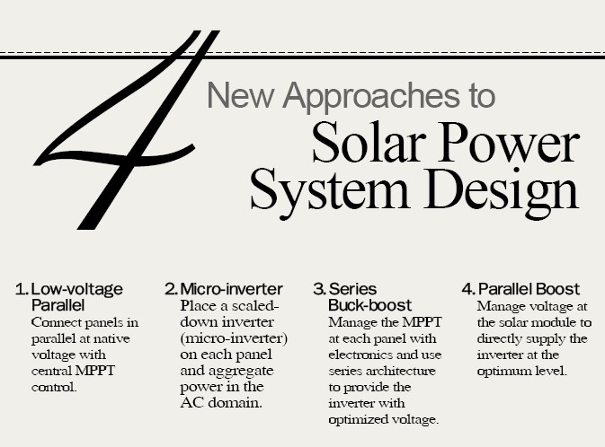
Smart people in all parts of the industrialized world have been analyzing this situation, and several alternative approaches to solar power system design are now available; each addresses the physical requirements of the solar modules in a different way. The four main methods are:
1. Low-voltage Parallel: Connect panels in parallel at native voltage with central MPPT control.
2. Micro-inverter: Place a scaled-down inverter (micro-inverter) on each panel and aggregate power in the AC domain.
3. Series Buck-boost: Manage the MPPT at each panel with electronics and use series architecture to provide the inverter with optimized voltage.
4. Parallel Boost: Manage voltage at the solar module to directly supply the inverter at the optimum level.
Each of these methods offers a certain level of improvement over the existing state of the art, but all have technical hurdles of their own. And all of them are subject to the balancing of their benefits versus their costs in both dollars and power. Let’s look at them in more detail.
Low-voltage Parallel
Simply connecting the individual modules in parallel and managing their power point from a central inverter can achieve efficient MPPT management if the modules are all closely matched for the power curves. The first challenge with this method, however, is that the native voltage of the solar modules is very dependent on the materials and architecture of their individual cells. Currently in the market we see modules with voltages ranging from 12 volts up to over 200 volts DC. In addition, each panel can see voltage swings of 30% and more; a 200-volt system could exhibit a swing of over 60 volts in what it presents to the inverter.
This creates several challenges. If an inverter is supplying a 208 Volt AC output, it needs an input voltage above that level to optimize its conversion process. This is normally accomplished with a boost circuit that takes the incoming voltage and boosts it to the optimal level for the inverter’s internal conversion mechanism. Even though this is a DC-to-DC conversion, it does reduce the overall efficiency of the system. This is in addition to the efficiency hit in converting the power from DC format to AC format.
These limitations can be solved by creating multiple operating modes, each of which is optimized for a specific window of operation. However, the major drawback of this approach is the power loss from heat dissipated by the wire used to transport the power. This is referred to as the “I squared R loss” which refers to the formula to determine the heat loss of a conductor (see Figure 1).
The square of the current times the resistance of the wire is the heat loss; the higher the current of the conductor, the more loss the system experiences (see Figure 2). This method also has a high ratio of current density to the power actually delivered. This requires heavy conductors compared to a high-voltage system carrying the same amount of power. This is because voltage and current are inversely proportional as they relate to power; as voltage goes higher, the current will be lower for the equivalent amount of power being transported.

Figure 2. I2 R losses for 100 ft of #10 AWG Wire (Source:eIQ)
Micro-inverters
The next option is the micro-inverter. This is the first of the distributed Maximum Power Point Tracking (MPPT) solutions. It connects directly to the module and handles the relationship of voltage and current at that point. Micro-inverters have the attractive quality of allowing a single module to deliver power in line-level AC; with this solution, usable power is available right at the module itself. The other big benefit of the micro-inverter is that all of the wiring is AC, which is a more common method for transporting power.
The downside of the micro-inverter is that you are limited to single phase line-level voltage, which is usually 208VAC or 240VAC. The other drawback is that each micro-inverter becomes a grid connection point. This means that each unit has to manage all grid connect issues. On a more strategic level, this approach also distributes the least reliable component of the solar power system throughout the entire array. This could have serious ramifications for maintenance of systems as they age.
Series Buck-boost
Distributed MPPT control can also be achieved by attaching a piece of dedicated electronics to each module. Once we marry electronics to the module, we can look at also doing some conditioning of the output power from the module. We are starting to see some offerings hit the market that allow modules to be connected in series, with a much more predictable effect on the voltage production of the panel or modules. This breakthrough helps to alleviate some of the mismatch and shading issues that plague our current state of the art.
The drawback of this approach is that it requires the distribution of electronics out to every module in the array. With this technology we are also still left with the issues relating to having to wire our array in series and keep all of the series strings in balance. This places additional load on our system design.
Parallel Boost
The last approach provides all of the benefits of distributed MPPT, while also continuously supplying the inverter with the exact level of voltage it requires to be able to create line-level AC. This requires the voltage booster on each module to match the module’s output voltage to whatever the inverter required. The primary issue with this approach is the efficiency of converting the voltage from a lower to higher levels.
A higher voltage is better for many reasons, and especially impacts the balance of systems cost. This is because the higher voltage operation allows for a much lower current for the same power. A simple comparison: to deliver 5 kW of power at 200 volts, we will have to accommodate 25 amps (see Figure 3). Providing that same power at 600 volts requires accommodation of only 8.3 amps.
In this case, three times as much power can be handled by the same piece of wire. A consistent voltage window at a higher potential also allows the inverter to be simpler in design, operate with a greater degree of efficiency, and place less stress on its components.

Figure 3. Current density for 5 kW circuit (Source:eIQ)
On the whole, solutions that enable parallel architecture create an opportunity for designers of solar systems to think differently about their craft. Using a parallel solar connection scheme will allow a system designer much more flexibility in module location--achieving exact matches in angle, shading, and reducing impact of issues in other areas. A parallel array also does not require the use of strings, or the balancing of modules on a string. Instead of string loops, a parallel system uses wire runs, much the same as running a lighting system.
The main benefit of eliminating strings is that voltage management is taken care of at the module level, by the panel that normalizes the power onto the bus. Technologies like the voltage boost or the micro-inverter will also allow you to connect different PV technologies on the same power bus. This can be very useful for technologies that might have different characteristics such as building-integrated PV systems. Similarly it enables connection of PV using different inclinations and orientations to the sun, and also manages shaded panels much more effectively than a series array. Another great side benefit of these technologies is that they provide monitoring detail down to the module on real-time system operation.
These new technologies will change the way solar systems work. They will enable us to build solar systems that are more resilient to environmental conditions, have higher availability, and are much more fault tolerant than the current state of the art. But most importantly, the distribution of electronics into the solar array also provides the opportunity to gather more data on the operation of the system, and provide operators with a much richer detail of the real time operation of these solar systems. This can only serve to help increase the predictability of the system’s output. Indeed, having a robust long-term operational history of an array can clearly increase its value as an asset.
Michael Lamb is Vice President Business Development of eIQ Energy (http://%20eiqenergy.com/) Lamb served seven years as a principal at Cornerstone Venture Partners, where he oversaw funding efforts for international renewable energy initiatives and helped companies create and manage strategic partnerships. He has over 8 years of experience in the energy management field and has held VP level alliance-building positions at companies in the global telecom and multimedia technology sectors.
For more information, please send your e-mails to .
ⓒ interpv.net All rights reserved
|

.jpg)