By Clive Lee
 What Energy Arrives at the Earth’s Surface? What Energy Arrives at the Earth’s Surface?
The energy emitted by the sun is 3.72 x 10²⁰ MW, which equates to a radiative power of 63 MW per m² of its surface. At the mean distance between earth and sun of approximately 150 million kilometers (1 Astronomical Unit, AU) the irradiance reaching the outside of the earth’s atmosphere, normally to the sun’s beams, is known as the Solar Constant (Eo). The 1982 value currently used by the World Meteorological Organisation (WMO) is 1,367 W/m2. However, the value obtained by NASA from extra-terrestrial measurements in 2008 is 1,360.8 ± 0.5 W/m2.
Actually, it is not constant. The earth’s elliptical orbit reaches the point nearest to the sun (Perihelion─147.5 million kilometers) around January 4th. 6 months later, around the 4th of July, it reaches the farthest distance from the sun (Aphelion─152.6 million kilometers). This means that the direct solar radiation reaching the earth’s atmosphere is 6.6% more intense in January than it is in July. Also, this changes by up to 0.1%, depending upon the sun spot activity cycle of between 9 and 12 years.
Surprisingly, the average temperature of the whole earth is about 2.3°C higher at Aphelion than at Perihelion, even although it is further away from the sun. This is due to the axial tilt and the distribution of land and sea on the earth’s surface.
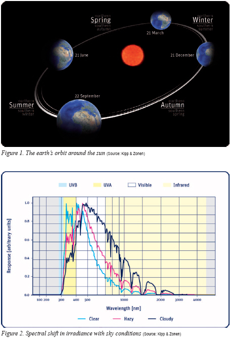
Figure 1 shows the dates for the Winter and Summer Solstices (the shortest day and longest day in the Northern Hemisphere). These do not correspond to Perihelion and Aphelion because the earth’s axis of rotation is tilted by 23.5º, which is the latitude of the Tropics of Cancer (North) and Capricorn (South). Between the Solstices are the Spring and Autumn Equinoxes.
The sun provides over 99.98% of all energy to the earth’s surface, the rest is from internal geothermal sources. The sun appears to us to be distant and small (it subtends an angle of 32 minutes of arc). Therefore, the beam of radiation arriving at the earth’s surface is almost parallel. The angle of incidence of the solar radiation is changing continually as the earth is circling around the sun and also spinning around its own axis.
When the sun is directly overhead, its beam of energy is concentrated upon the smallest possible area of the earth’s surface. However, when the sun is lower in the sky, its beam strikes a horizontal surface obliquely, and is spread out over a larger area. The amount of energy per unit area is thus reduced as the sun moves lower in the sky. The ratio of radiation intensity to angle of incidence may be described as a cosine function.
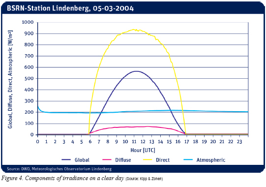
The amount and type of radiation falling on the surface also depends upon the changing characteristics of the atmosphere, which has a considerable influence on the intensity and spectrum of solar radiation reaching the ground. When passing through the atmosphere, extra-terrestrial solar radiation is reduced by scattering and absorption caused by air molecules, aerosol particles, water droplets and ice crystals in clouds. The spectrum of solar radiation received on top of a mountain in a remote region can differ markedly from the spectrum received in an industrial or urban area near sea level. Figure 2 illustrates this effect.
The solar radiation reaches its highest intensity when the sun is directly overhead at a ‘solar zenith angle’ (θ) of 0° and the thickness of the atmosphere is at its minimum. The lower the sun’s position is in the sky, the more atmosphere the radiation must pass through, and so more radiation is scattered and absorbed. Less radiation reaches the earth’s surface and the spectrum of the radiation also changes.
.jpg) When the sun is directly overhead the atmospheric depth/thickness is at a minimum, and is defined as having a Relative Air Mass of 1.0 for that location. As the sun moves down towards the horizon, the air mass increases. At the horizon (solar zenith angle 90°) the atmospheric depth (thickness) is approximately 11 times larger than at the shortest path (see Figure 3). When the sun is directly overhead the atmospheric depth/thickness is at a minimum, and is defined as having a Relative Air Mass of 1.0 for that location. As the sun moves down towards the horizon, the air mass increases. At the horizon (solar zenith angle 90°) the atmospheric depth (thickness) is approximately 11 times larger than at the shortest path (see Figure 3).
The radiation significant for processes on earth extends from 280 nm (nanometers, 10-9 m) to 3000 nm and from 3 μm (micrometers, 10-6 m) to 50 μm in the bands shown in Table 1. The maximum intensity of the solar spectrum occurs at 500 nm, towards the blue end of the visible. Infrared radiation is split into Near Infrared (NIR) and Far Infrared (FIR). FIR is not emitted from the sun, it comes from the sky; atmosphere and clouds that absorb short-wave radiation, heat up, and re-emit radiation in the far infrared as heat; and from the earth’s surface.
What Is ‘Global’ Irradiance?
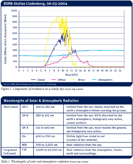
Global Horizontal Irradiance (GHI, Eg↓) is the total short-wave radiation from the hemisphere above a horizontal plane surface. This is a combination of the Direct Irradiance from the sun (E), corrected for the angle of incidence (θ), and the Diffuse Irradiance (Ed↓) from the sky and atmosphere - according the equation Eg↓ = Ecosθ + Ed↓. All these parameters are measured in units of W/m2.
Figures 4 and 5 show the difference between a clear sky day and a day with clouds coming over at mid-morning. In both cases, ‘Atmospheric Radiation’, is the Far Infrared (FIR) component.
In certain partially cloudy sky conditions, it is possible for the global solar irradiance to temporarily exceed the extraterrestrial Solar Constant of 1,360.8 W/m2, but 1,500 W/m2 is the practical maximum under natural sunlight.
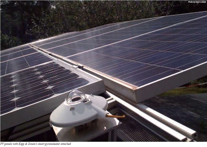
How Do We Measure It?
Pyranometers are defined by ISO 9060:1990 ‘Solar energy─Specification and classification of instruments for measuring hemispherical solar and direct solar radiation’ as the instruments for the measurement of hemispherical (global) solar radiation in a wavelength range from at least 300 nm to 3,000 nm. Similar requirements can be found in the World Meteorological Organization (WMO) Guide to Meteorological Instruments and Methods of Observation, currently at the 7th Edition, 2008.
Pyranometers are categorised by their performance such that there are scientific precision instruments as well as those for routine measurements. ISO 9060:1990 has three categories, as shown in Table 2.
Please note that it is no longer encouraged to use terms such as ‘accuracy’ or ‘error’, except in the most general sense, for measurement performance. These are poorly defined terms. The term ‘uncertainty’ should be used where appropriate. The International Standards Organisation (ISO) Guide to the Expression of Uncertainty Measurement (GUM) provides a standard method for the determination of uncertainty in measurement.
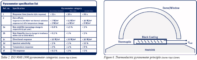
Photoelectric sensors (photodiodes) cannot meet the ISO 9060 and WMO spectral range and selectivity requirements, so compliant pyranometers use the thermoelectric detection principle. The incoming radiation is almost 99% absorbed by a horizontal blackened surface over a very wide wavelength range. The resulting increase of temperature is measured via thermocouples connected in series or series-parallel to make a thermopile. The active (hot) junctions are located beneath the blackened receiver surface and are heated by the radiation absorbed in the black coating. The passive (cold) junctions of the thermopile are in thermal contact with the pyranometer housing, which serves as a heat-sink.
It is necessary to protect the black detector coatings against external influences which may affect the measurement; such as precipitation, dirt and wind. The principle is illustrated in Figure 6.
Nearly all pyranometers use an optical quality glass for their hemispherical single or double domes. Depending upon the glass the transmission is from 300 nm, or less, to about 3,000 nm. Double domes give better stability under dynamically changing conditions by further ‘insulating’ the sensor surface from environmental effects such as wind and rapid temperature fluctuations.
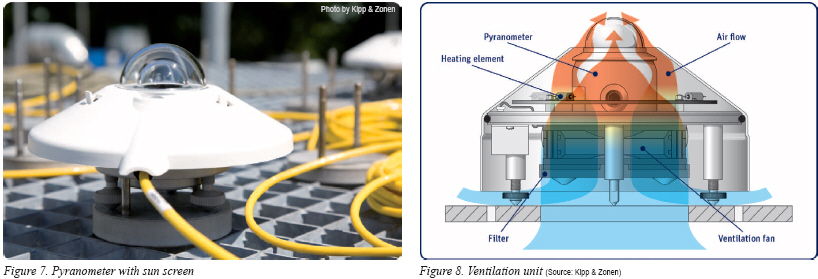
The shape of the dome, and the refractive index of the material, improves the response of the sensor when the sun is close to the horizon, ‘bending’ the incoming radiation beam. The highest specification pyranometers use Quartz domes for a wider spectral response. The higher refractive index further improves the directional response and better thermal conductivity than glass provides other performance benefits. A typical pyranometer is shown in Figure 7.
What Is the Pyranometer Output?
Thermopile pyranometers do not require a power supply because the detector generates a small voltage in proportion to the temperature difference between the black absorbing surface and the instrument housing. This is of the order of 10 μV (microvolts) per W/m2, so on a sunny day the output will be around 10 mV (millivolts). Each pyranometer has a unique sensitivity defined during the calibration process, which is used to convert the output signal in microvolts into global irradiance in W/m2.
The uncertainty of the measurement is affected by a number of factors that are functions of the pyranometer design and construction, the most significant are:
-Temperature response,
-Directional response,
-Spectral range,
-Response Time,
-Non-stability,
-Non-linearity,
-Zero Offsets.
The better the quality of the pyranometer, the smaller are these effects. The very best pyranometers with glass domes can achieve an uncertainty in the daily total of global irradiance of less than 2%. The best model currently available uses quartz domes and can measure within 1%.
What Is the Benefit of Ventilating a Pyranometer?
Of course, getting the best performance from a pyranometer depends on regular maintenance, in particular keeping the dome clean. It will be appreciated that dirt, pollution, dew, frost or other obscuration will significantly affect the measurements. Ideally, the dome should be regularly cleaned but this is not always possible. The availability of ‘good’ data can be significantly increased by using a ventilation unit as shown in Figure 8. This blows filtered air over the pyranometer dome to help keep it clean and can apply heating when required, to remove precipitation. Ventilation also reduces thermal offsets in the pyranometer, improving performance.
What Is New in Pyranometers for Solar Energy?
Good quality meteorological data loggers are designed with inputs able to measure down to 5 μV, to take the very small pyranometer output signal directly, and can make the conversion to W/m2. However, in solar energy applications most of the industrial data acquisition and control systems used do not have the necessary resolution or ‘accuracy’ and the signal cable length is limited to about 100 m. Voltage or current amplifiers (4-20 mA) can be used to boost the signal or allow longer cable lengths, but these can be difficult to connect, and may degrade the performance if not carefully designed. Industrial sensors used in solar energy installations now have digital interfaces and the traditional pyranometer is the odd one out.
To solve these interfacing problems a new generation of smart pyranometers, is now available.
The SMP Series from Kipp & Zonen of Delft, the Netherlands are the world’s first smart pyranometers with built-in intelligence. Building on the proven CMP Series design and technology that is used around the world in meteorology and climatology networks and in solar energy, they have integrated digital signal processing and are optimised for solar energy applications. Kipp & Zonen has developed a smart interface that features Modbus® data communication for connection to programmable logic controllers, inverters and digital control equipment. Amplified analogue outputs are also included for systems that have 4-20 mA current loop or high level voltage inputs.
The smart interface not only provides versatile outputs. An integrated temperature sensor and polynomial functions provide correction for the temperature sensitivity of the detector. The response time has been digitally enhanced and the output ranges are standardized. Using Modbus® a range of instrument status and configuration information is available, with user-selectable options.
SMP pyranometers have extremely low power consumption so that internal heating does not affect the detector performance. They operate from a wide range of supply voltages, making them ideal for power-critical applications. There are two versions, one has an analogue output of 0-1 V, the other is 4-20 mA. Both have a 2-wire RS-485 interface with Modbus® (RTU) protocol that can operate over cable lengths of hundreds of metres. All the outputs are protected against short-circuits.
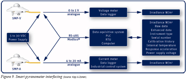
The interfacing possibilities are shown in Figure 9.
The pyranometers are individually addressable and can be daisy-chained in networks with other Modbus® sensors, saving on cabling costs. The high quality waterproof cable connector and standardized outputs make it easy to interchange instruments for recalibration. SMP3 is an ISO 9060 Second Class pyranometer and SMP11 exceeds the requirements for Secondary Standard. All Kipp & Zonen pyranometers are fully traceable to the World Radiometric Reference (WRR) in Davos, Switzerland.
Clive Lee has been with Kipp & Zonen (www.kippzonen.com) in solar radiation and atmospheric science instrumentation since 1998. Previously, he was the Senior Technical Specialist for the Air Quality Monitoring Section of Siemens Environmental Systems in the U.K., and prior to that worked in gas analysis and monitoring with the leading company in the sector, now Honeywell Analytics.
For more information, please send your e-mails to pved@infothe.com.
ⓒ2011 www.interpv.net All rights reserved.
|


.jpg)