By Umar Lyles, Brian Lum-Shue Chan, Yogesh Ramadass
.jpg)
There are several methods for harvesting energy from the environment. Of these, solar energy harvesting is of particular interest because it is readily available. Plus, advancements in the efficiency of solar harvesters are increasingly making this an attractive alternative. In order to make the best use of this technology, the designer needs to determine how best to extract energy from the solar harvester in an effective manner.
To understand what additional challenges a solar charger poses, study the I-V curve for a typical solar cell (Figure 1). Here you can see that there are a range of different power points the panel can operate at, as opposed to the single point you would see for a typical wall charger. Clearly, from the curve, if the panel is operating at either point A or B, there would be no available output power. Ideally, the goal is to operate the panel at point C; the Maximum Power Point (MPP) of the solar cell.
Depending on the solar irradiance or temperature, the MPP can move relative to the panel voltage. Several methods are available for calculating or approximating this power point so that a system can always operate the panel at point C1). Assuming a system perfectly regulates the input to MPP, the only question that remains is how to most efficiently transfer power from the panel to a charge storage element. Because the voltage of the storage element is unknown during charging, the power converter needs to be capable of converting any voltage drop between panel and storage element to a gain in charge current in order to achieve high efficiency. Several switching converter topologies with greater than 90% efficiency are available that fit this description. With this high level assessment, you can conclude that the most effective system for solar charging consists of some type of ideal buck converter which employs Maximum Power Point Tracking (MPPT).
Unfortunately, because of the external components required for a buck converter (most notably an external inductor) and the circuit complexity for precision MPPT, the buck converter with MPPT solution tends to be very expensive. Also, most MPPT circuitry consumes additional power which reduces the overall efficiency. However, knowing the ideal performance target, it is possible to evaluate less expensive and less complicated systems such as linear or passive (diode) charging. Now let’s analyze how close to the ideal target the systems can get when additional optimization techniques are employed.
.jpg)
Linear Charging
For a linear system, the input and output current is the same, but there is a voltage drop between the charging source and the battery. For example, with a 5V charger and charging current of 500 mA, a storage element with a voltage of 4V in an ideal linear charger sees a loss of 500 mW of power--or 20% of the charger’s energy. It is not uncommon, however, to see chargers that employ linear systems because, given the fact that charge current is not limited by the charging source, charging times remain unaffected.
For a solar charger, there is a key difference in that it is common for the charging source to limit the current delivered to the load. For example, under certain conditions a panel has a short circuit current of 200 mA and an open circuit voltage of 5V. If the battery is at 4V and the system current limit is greater than the 200 mA the panel can deliver, the panel voltage collapses down to the 4V at which that battery is operating. At this point, the power at the panel is equivalent to the power delivered to the battery and we should achieve greater than 90% efficiency as seen in our ideal system model of a buck converter. Although high efficiency is achieved, there is no way to regulate the input to the MPP. This limits the power that the panel can deliver. With a switching power converter with MPPT, the panel does not fully collapse and the higher voltage shows up as a gain in the charging current after the power conversion. Because of this, in theory, it seems that the linear solution is not preferred for solar charging. In practice, however, for most cases, it performs just as well or better than a switching regulator. This is due to the fact that most storage elements operate over a limited voltage range for the majority of their life spans. Using this knowledge, it is possible to select a solar panel and storage element that are optimized for one another such that the linear charger always operates near the maximum power point.
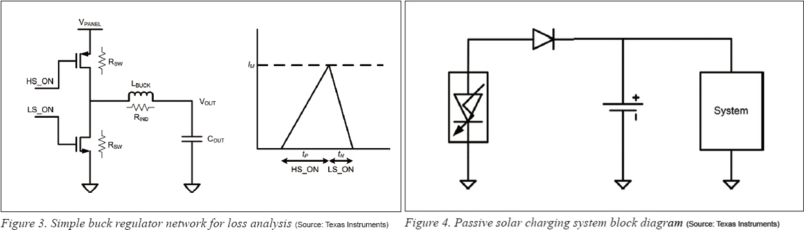
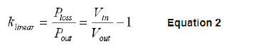
So far the discussion has centered on the ideal limits that could be achieved in the charging system. However, taking into consideration some of the physical limitations of the system, there are certain conditions under which the linear system can actually perform better than a switching solution. Assuming that the quiescent current for both systems can be made equivalent, the percentage losses due to conduction of both systems can be compared. For a typical buck regulator operating in the discontinuous conduction mode (Figure 3), the percentage of energy lost to energy delivered to the output is given by Equation 1:
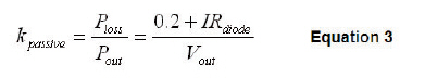
By comparison, for a linear regulator the percentage loss is a function of voltage only (Equation 2). Therefore, when the solar panel collapses such that Vin approaches Vout, the losses approach zero in a linear system.
When using a solar panel in conjunction with a charge storage element that has an operating voltage range near the maximum power point of the panel, a linear charger can deliver just as much power (in some cases more) then a switching regulator with MPPT. Additionally, the reduced cost and complexity, elimination of switching noise, and lower input voltage ripple and output current ripple make linear charging a good choice for energy harvesting systems that have charge storage elements with limited voltage range, for example, rechargeable batteries. In harvesting systems where the charge storage element can span a wide voltage range, as in the case when using a super capacitor, a switching regulator with MPPT may be a better choice, if it is expected that the charge storage element voltage will be operating away from the solar panel’s MPP for a significant percentage of the systems lifetime.
Passive Charging (Diode)
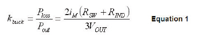
The simplest and cheapest solar charging system consists of a reverse blocking Schottky diode in series with the solar panel connected directly to the charge storage element (Figure 4). In this system there is no way to actively regulate the solar cell to its maximum power point. Similar to the linear charging case the solar panel and charge storage element should be optimized to ensure the system typically operates near the MPP (Figure 2).
Assuming a diode voltage drop of 200 mV the percentage of energy lost is given by Equation 3.
Because the losses using Equation 3 are dominated by the physical limitations of the Schottky diode voltage, the diode solution, when compared to linear or switching solutions, will be less efficient so long as Vdiode remains greater than IRsw. This holds true when the switch resistance is made small and charging currents are large enough that the diode saturates. In cases of very small charging currents that are less than ~10 uA, the diode voltage drop becomes much less--making this solution more viable. In addition to the efficiency losses, a completely passive solution may be problematic for systems that utilize a battery as the charge storage element. This is because, without the addition of another IC, there can be no battery management control. Without battery management, the solar cell must be selected such that the highest voltage it can possibly output will not over charge the battery and damage it. This design constraint for best case panel conditions ultimately limits system performance under normal or low-irradiance conditions.
Ideally, to get the best performance when architecting a solar charging system, a system should operate the panel near its maximum power point and convert the panel power to the storage element with maximum efficiency. In practice, most systems have a charge storage element that has either a limited operating voltage range or a very small capacity. In cases where the voltage range is limited, you can achieve near ideal performance with a linear regulator by selecting a panel where the maximum power point is centered over the charge storage operating range. In cases where the voltage range is wide but the capacity is small, the cost and simplicity may also justify using a linear charging system.
If you expect that the operating point of the storage device will not be near MPP for a significant amount of time, a switching regulator is recommended. For the cheapest and simplest solution, a passive diode charger can be used, but it comes at a cost of degraded performance and lacking any battery monitoring control. Take a look at the linear chargers that have been optimized for medium power ( >10mA < 1 A) applications.
Umar J.Lyles is an analog/mixed signal IC designer with the Nano Power and Harvesting group at Texas Instruments (www.ti.com). He received his BSEE and MSEE from Arizona State University, Tempe, Arizona.
Brian Lum-Shue Chan is a Design Manager with the Nano Power and Harvesting group at Texas Instruments. He received his BSEE and MSEE from Georgia Institute of Technology.
Yogesh Ramadass is an analog/mixed signal design engineer with the Nano Power and Harvesting group at Texas Instruments. He received his SM and Ph.D. degrees from the Massachusetts Institute of Technology.
REFERENCES
1) Hohm, D.P.; Ropp, M.E.; ‘Comparative Study of Maximum Power Point Tracking Algorithms Using an Experimental, Programmable, Maximum Power Point Tracking Test Bed’ Photovoltaic Specialists Conference, 2000
For more information, please send your e-mails to pved@infothe.com.
ⓒ2011 www.interpv.net All rights reserved. |


.jpg)