By Elie Nasr
.jpg)
 The growth of the renewable energy industry, in particular solar and wind, has been explosive over the past decade. It has been fueled worldwide by generous incentives and subsidies from various governments and broad acceptance of policies advocating greater reliance on green power sources. One particular country that currently accounts for over 50% of total worldwide installed capacity of Solar Photovoltaic (PV) installations is Germany, with more than 12 GW of installed PV estimated by the end of 2010. While Germanys target is to consume 47% of the country’s energy demand from renewable sources by 2020, 14% of which is planned for solar PV, the level of integration from these sources on the grid presents a substantial threat to system reliability. The growth of the renewable energy industry, in particular solar and wind, has been explosive over the past decade. It has been fueled worldwide by generous incentives and subsidies from various governments and broad acceptance of policies advocating greater reliance on green power sources. One particular country that currently accounts for over 50% of total worldwide installed capacity of Solar Photovoltaic (PV) installations is Germany, with more than 12 GW of installed PV estimated by the end of 2010. While Germanys target is to consume 47% of the country’s energy demand from renewable sources by 2020, 14% of which is planned for solar PV, the level of integration from these sources on the grid presents a substantial threat to system reliability.
While various grid codes have been in place for wind and other types of renewable energy generation for some time now, it was only two years ago, in June 2008, that the German Federal Association for Energy and Water (Bundesverband der Energie- und Wasserwirtschaft, BDEW) imposed new guidelines for PV systems connected to the medium voltage network.
In the U.S., the California Independent System Operator (CalISO) board approved on May 20, 2010 new proposed interconnection standards for large PV generation (≥20 MW) that included requirements similar in principle to the ones delineated in the BDEW guidelines.
As PV systems become more common in number but also increase in size, ISOs and Regional Reliability Coordinators are faced with tremendous challenges related to operations, planning, and resource scheduling and coordination in order to ensure a high level of reliability with larger amounts of variable power generation on the grid.
The North America Electric Reliability Council (NERC) Integration of Variable Generation Task Force (IVGTF)1) report2) recognized that ?o accommodate higher penetration of variable generation, changes will be required to traditional methods used by system planners and operators in order to maintain the reliability of the bulk power system on an ongoing basis. Making these significant changes will be challenging for the industry, however, they will be needed to continue maintaining bulk power system reliability while integrating large amounts of variable generation.?
While there have been various changes related to variable generation that correlate to interconnection and operational requirements identified by reliability entities, a few are as particularly significant to the development of current and future PV inverter technology, as Power Factor Adjustment and Low Voltage Ride-through applicability to PV generation.
Power Factor Requirement
Inverters form the heart of every solar energy system. A solar PV system depends on the inverter to make use of the energy generated from the modules. Inverters convert the direct current generated by the solar module into grid-acceptable alternating current. For large-scale commercial systems, inverters convert the DC power provided by the PV source circuits to AC power at three-phase output voltages in the range of 200 V to 480 V, depending on the particular inverter model.
In a utility-scale photovoltaic power plant located in the U.S.A., the AC output of the inverter would normally connect to a step-up transformer for direct connection to a medium voltage substation (up to 34.5 kV). For transmission interconnected plants, a final transformation to high voltage (HV, 69 kV, 115 kV, 138 kV , 230 kV) or extra high voltage (EHV, 345 kV, 500 kV, 765 kV), as required for the particular transmission network interconnection, would occur at a collection substation.
The energy delivery point to the utility network is known as ‘Point of Interconnection (POI)’ and is sometimes referred to as Point of Common Coupling or PCC.
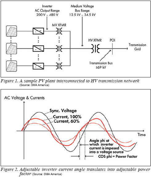

Figure 1 illustrates the delivery point scenario to a utility HV transmission network.
The main reason why the POI is of particular interest is that the proposed interconnection standards require maintaining a power factor range at that point. In its final recommendation, California ISO, for example, is proposing 0.95 leading/lagging at the point of interconnection.
Power factor is a measure of real power in relation to reactive power. A high power factor means that more useful power is being taken or produced relative to the amount of reactive power. A lower power factor means that there is relatively more reactive power taken than real power. Power systems engineer refer to the ability to adjust power factor at the POI as operating in the ‘Power factor control mode’ A lagging power factor means the need to add or inject VARs into the transmission bus in order to assist in voltage support, while a leading power factor requires the need to absorb or consume VARs from the bus. The utilities and reliability coordinators are looking at inverters to provide this capability and be able to control the power factor at the POI to the specified range.
For inverter manufacturers, this presents a paradigm shift from the unity power factor that we are used to seeing in most specification sheets. However, the ability to supply (or absorb) VARs to comply with power factor interconnection requirements is well within the technical capabilities of the inverter power electronics. After all, from a waveform perspective, this requirement translates into a shift in angle between the voltage and current instead of them being in synch, as illustrated in Figure 2. Furthermore, the ability to supply or consume VARs is totally independent of the DC system side (except for the small amount of power needed for the inverter controls) so theoretically inverters should be able to supply VARs even at night.
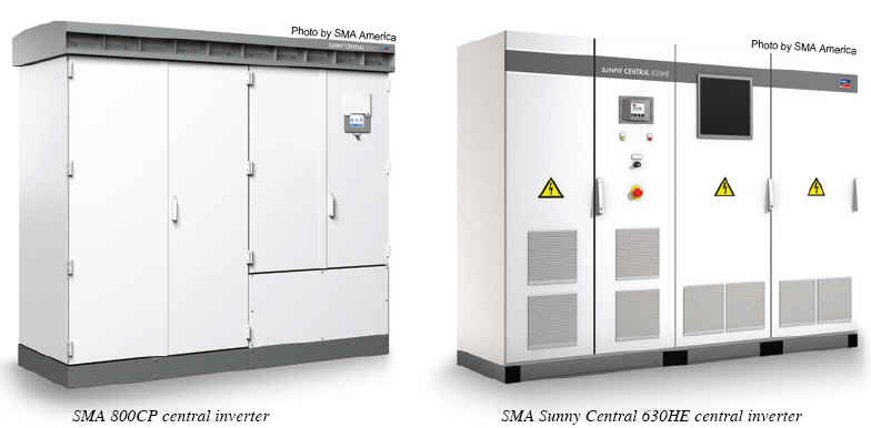
The newly released SMA CP series of central inverters, for example, are actually rated in kVA in lieu of kW specifically to address the PF requirement and emphasize their ability to provide VAR support.
To illustrate with an example, the Sunny Central CP inverters, are designed to be not only the current largest single central inverters in the market, but also scalable to various kVA ratings depending on environmental conditions and minimum MPP input voltage.
For ambient temperature ≤25°C, the Sunny Central 630CP central inverter (rated 700 kVA), is capable of providing 700 kW and 0MVAR with unity power factor (PF=1) and with a 0.9 power factor (PF=0.9) lagging or leading; the 700 kVA is able to provide around 630 kW and ±305 kVAR. This feature is demonstrated in the Pythagorean Theorem of Figure 3.
The requirement for PF adjustment and control is well within the inverter technical capabilities. Although substantial impact on inverter power electronic design and also DC system design needs to be taken into account when deviating from unity power factor, various inverter manufacturers have made the necessary design adjustments to accommodate this requirement; however, one should exercise caution when analyzing the inverter data sheet and make sure that the nameplate kW rating of the inverter is not derated by the power factor deviation from unity.
Low Voltage Ride-Through (LVRT) Requirement
In 2005, and in its final ruling, the Federal Energy Regulatory Commission (FERC) adopted a Low Voltage Ride-Through (LVRT) standard for large wind generation interconnection (≥20 MW). This order, known as FERC Order 661-A requires that generators remain connected to the grid during a fault clearing time (which is a time period of approximately four to nine cycles) that occurs on the transmission system.
The FERC ruling was supported by the NERC argument for maintaining grid stability on the bulk power system. According to NERC, a fault occurring on a transmission line near a plant could cause the voltage at that point to drop to zero for this clearing time. NERC stated that if the plant is allowed to disconnect when the voltage drops to a very low level, the loss of the single grid element (the transmission line) would be compounded by the loss of the real power, and any reactive power, produced by the plant and that would constitute a ‘double contingency event’ (loss of line and generator).
NERC asserted that this ‘double contingency event’ violates Reliability Standard TPL-002-0:
“TPL-002-0 seeks to ensure that the future Bulk Power System is planned to meet the system performance requirements, with the loss of one element, by requiring that the Transmission Planner and Planning Authority annually evaluate and document the ability of the transmission system to meet the performance requirements where an event results in the loss of a single element. Generally, TPL-002-0 requires that the Planning Authority and Transmission Planner demonstrate through a valid assessment that the system performance requirements can be met in the event of a loss of a single element.”
For PV grid-connected systems, no standard for large systems or high penetration in NERC regions has been imposed yet, mainly because most installations in North America have been residential and commercial interconnections to distribution networks. Further, most North America PV installations have been connected to distribution level governed by IEEE 1547 standards, which do require disconnection from the grid during faults or even large voltage fluctuations.
Thus far the level of PV on the grid has been small enough that it did not pose any threat to reliability on distribution or on transmission systems, until recently. CalISO now states that it has over 17,000 MW of variable generation capacity in the ‘serial group’ and ‘transition cluster’portions of its interconnection queue for which system impact studies should have been completed by June 2010.
In Germany, on the other hand, when the MV Directive was put in place in June 2008 by the BDEW, a clear requirement for voltage ride-through was laid out on PV plants based on Transmission Code 2007 Section 3.3.13.5. The LVRT requirement is summarized as follows:
-Generating units must not disconnect from the grid in the event of voltage drop to 0% of nominal voltage for a period of 150msec;
-If after 150 msec, the voltage does not recover to 30% of nominal, then no requirement to stay connected is enforced.
The inverter behavior for the BDEW LVRT requirement is illustrated in the graph shown in Figure 4.
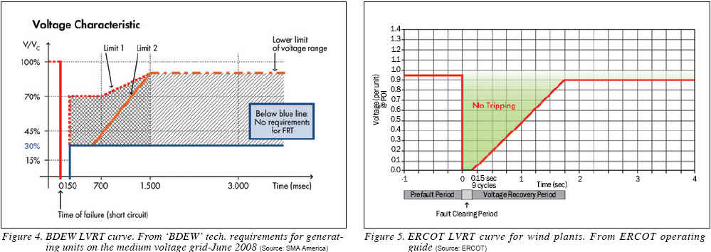
According to BDEW, if the voltage drops to values above Borderline 2 and below Borderline 1, generating units shall pass through the fault without disconnecting from the grid. Below the blue line, there is no requirement to stay connected and if the voltage recovers to above Borderline 1, then they may resume normal operations. The behavior during the recovery is left to be defined by the utility for the specific interconnection point.
Similarly, CalISO, in its new interconnection standards, recommended extending FERC Order 661-A to all generator types including solar PV. While the LVRT clearing time and plant behavior is defined by the transmission operator of the POI, the PV inverter may be designed and programmed with a default characteristic curve to follow the LVRT requirement (assuming no IEEE 1547 compliance).
Once the hardware and power electronics are properly designed and built to support the LVRT feature, which is not a trivial task, adapting the inverter behavior to other LVRT characteristic curves is then a simple matter of parameters setting within the firmware of the inverter and should not require any further hardware changes.
To illustrate with an example, inverters from the SMA Sunny Central CP series are programmed with a default curve that follows the one illustrated in Figure 4. Adapting the same inverters to the curve illustrated in Figure 5, which is based on the ERCOT wind LVRT requirement, would involve modifying certain parameters such as the frequency setting from 50 Hz, to 60 Hz, or ‘0’ ride-through period from 7.5 cycles to nine cycles, etc. in the firmware of the inverter, testing the changes and then accepting them.
Challenges Ahead
While major design changes have been incorporated into inverters to promote their ‘grid friendly’ features, other challenges to grid reliability remain unanswered: the characteristic of PV intermittency; and the inability to control ramp rates.
Unlike wind, solar correlates better with peak demand of most power systems, thanks to its diurnal and seasonal patterns. Solar output normally peaks in the afternoon and in the summer so ‘peak shifting’ may be accomplished in a couple of hours.
However, solar PV plants do not involve rotating machines and therefore, do not have inertia. As a result, operating PV plants are susceptible to substantial ramps when rolling clouds shade a portion of the plant. A PV system can experience variations in output of ±50% in a 30 to 60 second time frame and ±70% in a five to ten minute time frame. Furthermore, ramps of this magnitude may be experienced many times in a single day during certain weather conditions.
Various research and development programs and studies are currently underway to address this particular issue with solar PV. And, while interconnection procedures and standards should recognize the unique characteristics of various generation technologies, the focus remains on the overall bulk power system performance rather than the performance of an individual generator.
Further, with current standards, widespread deployment of distributed variable generation has the potential to cause adverse impacts on grid performance. It may be time to take a second look at IEEE 1547 requirements for further evolution and reconciliation.
Despite the grid challenges facing utility-scale PV, the industry is adapting and there remain few technologies with as much potential to reshape our world. As Thomas Edison said in 1931,
“We are like tenant farmers chopping down the fence around our house for fuel when we should be using Nature’s inexhaustible sources of energy--sun, wind and tide. I‘d put my money on the sun and solar energy. What a source of power! I hope we don’t have to wait until oil and coal run out before we tackle that.”
Elie Nasr is a senior business development manager at SMA America (www.SMA-America.com), where he is responsible for the SMA’s North American utility-scale business-building efforts. Nasr has an extensive 25-year history in utility power-related fields.
REFERENCES
1) In December 2007, NERC’s Planning and Operating Committees created the Integration of Variable Generation Task Force and charged it with preparing a report to identify; 1) technical considerations for integrating variable resources into the bulk power system, and 2) specific recommendations for practices and requirements, including reliability standards that cover the long-term planning, operations planning, and real-time operating timeframes.
2) NERC IVGTF report is located at: http://www.nerc.com/docs/pc/ivgtf/IVGTF_ Report_041609.pdf
For more information, please send your e-mails to pved@infothe.com.
ⓒ2010 www.interpv.net All rights reserved.
|


.jpg)