BY UWE MICHEL, ALESSIO MAIOCCHI AND RONALD F.M. LANGE
Significant research has been performed in the PV arena1). However, the focus has been mainly on the development and improvement of the PV active materials. The encapsulation of these PV active materials, ensuring an efficient guiding of the sunlight and protecting the active PV materials from the harsh environment is often taken for granted. The most commonly produced PV modules are so-called glass-backsheet modules and consist of a 3 or 4 mm glass plate, an encapsulant (mostly EVA-based), crystalline cells and a backsheet (mostly a multiple-layer structure consisting of a polyester and a fluor containing polymer)2). The encapsulation or lamination of PV modules is most frequently carried out using a so-called flat-bed laminator3),4). A flat-bed laminator consists basically of a processing unit that is divided by a flexible (silicone) membrane in an upper and lower chamber. Both chambers can be evacuated individually and the module lay-up is normally heated by a heating plate. Commonly used heating technologies are an electrical heating system, an oil-based heating system or a hybrid electrical-oil heating system. The hybrid heating technology, using an electrical system assisted by heat carrier oil, is generally preferred due to the exceedingly homogeneous temperature characteristic obtained5).

Figure 1 a. Picture of a three-chamber laminator as well as a schematic representation of a flat-bed laminator showing the processing chamber divided in an upper and lower chamber by a flexible membrane and equipped with a heating plate (Source: 3S Swiss Solar Systems)
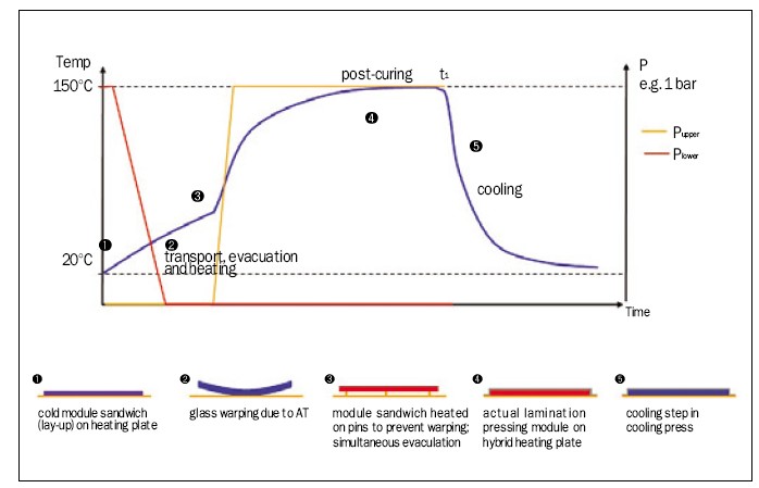
Figure 1 b. Variation of the temperature and pressure in time during the lamination cycle of a PV module (schematic presentation) as well as a schematic representation of the module during the lamination process (Source: 3S Swiss Solar Systems)
This homogeneous temperature characteristic enables a significant faster lamination process, as well as a more homogeneous cross-linking of the encapsulant and hence leads to high-quality PV modules. The lamination process using a flat-bed laminator is depicted in Figure 1. The cold module lay-up is inserted in the laminator (point 1). Due to the relative large temperature difference of about 100 -150 between the heating plate and the PV module lay-up upon insertion, glass warping is observed (point 2). The glass warping induces an inhomogeneous temperature profile between the center and edges in the module lay-up and has to be avoided if a homogeneous EVA cross-linking degree, and hence a high module quality, is aimed at. To cope with this glass warping, the flat-bed laminator is equipped with so-called pins and the module lay-up is heated gently and homogeneously in a first step on the pins without direct contact to the heating plate (point 3). In the meantime the lower processing chamber of the laminator is evacuated to remove the air and other volatile substances. The air is removed mainly to avoid bubble formation in the processed PV modules. After obtaining a homogeneous temperature and crossing the so-called EVA softening point (not to confuse with the glass transition temperature Tg), the PV module is directly pressed on the heating plate and the actual EVA cross-linking process is performed (point 4).

Figure 2. Schematic process of the three-chamber lamination process (Source: 3S Swiss Solar Systems)
The pressure application on the PV module is established by venting the upper chamber. As a result the flexible membrane, dividing the upper and lower chamber, is pressed on the PV module. Pressing the module lay-up on the heating plate results in an improved contact and hence in an improved heat transfer. The heating rate increases, the module is pre-sealed and subsequently the EVA post-curing process to the desired EVA cross-linking density, normally >80% as determined by the insoluble part in an aromatic organic solvent extraction, starts (point 5). A subsequent controlled cooling step (point 6) completes the lamination cycle and the stable PV module is ready for the post-lamination steps and testing. For completeness it is mentioned that the basic principles described above for a crystalline glass-backsheet PV module using EVA as an encapsulant are also valid for crystalline as well as the various thin-film glass-glass modules and the use of various (reactive and non-reactive) encapsulants as e.g., PVB, silicones, ionomers and polyolefin��s.

Figure 3 a. Temperature-time process curve of a lamination process: in a traditionally used two-chamber process the lamination cycle time producing a batch of modules is t1, whereas in the three-chamber process the lamination cycle can be splitted using a cycle time ��t1 and hence leading to a doubling of the output. (Source: 3S Swiss Solar Systems)
Lamination Process
In summary, the following basic steps exist in the lamination process: homogeneous heating of the module layup to reach the processing temperature of the encapsulant, pre-sealing of the module layup, post-curing of the encapsulant to ensure a stable laminate with a lifetime exceeding 25 years and finally a controlled cooling step.
To increase the PV module output as well as to increase the quality of the PV modules, the heating and the cooling step has been separated and realized in a two-chamber encapsulation process.6) Please note that the controlled cooling of the PV module in the cooling chamber is generally significantly faster compared to the heating, pre-sealing and curing step in the heated processing chamber.

Figure 3 b. Exploiting the three-chamber lamination process by applying different temperatures in the separate heating chambers leading to an additional cycle time reduction (here t2) and hence leading to more than doubling the output (Source: 3S Swiss Solar Systems)
Studying the lamination process in more detail focussing on the heated processing chamber, an additional separation step using two heated processing chambers should be possible, intrinsically leading to a doubling of the output.
The resulting three-chamber lamination process is operated as follows: a cold module layup is transported into the first-heated processing chamber, homogeneously heated on the pins, subsequently pressed on the plate and pre-sealed (Figure 2 a, b). After this pre-sealing step the pressure is released, the hot module is transported into the second heated processing chamber and post-cured by applying a pressure. Simultaneously, a cold layup is transported into the first-heated processing chamber (Figure 2 b, c). In the next concerted cycle, the post-cured module is transported from the second process chamber to the cooling press, the pre-sealed module from the first- to the second-heated processing chamber and a cold layup into the first heated processing chamber (Figure 2 c,d). Using this principle a doubling of the PV module output is obtained. In a two-chamber process the cycle time t1 is defined by the heated processing chamber where the module is heated, pre-sealed and post-cured (Figure 3 a). However, in a three-chamber process the cycle time is defined by the first heated processing chamber where the module is heated and pre-sealed, in Figure 3 a, depicted as ��t1. If, as an example, t1 is set at 16 min, a two-chamber process will produce every 16 min a batch of PV modules whereas a three-chamber process will produce every 8 min a batch of modules. Please note that an additional advantage of the three-chamber process is the significantly increased utilization of the cooling chamber.

Figure 4. Comparison of a traditional two-chamber lamination process (blue) with an optimized three-chamber lamination process (red) showing the reduced lamination cycle time of up to 70% with a significantly reduced footprint as well as a reduced energy consumption per produced PV module. (Source: 3S Swiss Solar Systems)
Three-chamber Lamination
The choice of materials, more specifically the thermal stability of the materials used in the PV module, limit the maximum processing temperature in the lamination step. As process temperature correlates with reaction rates and hence processing time, a decrease of the cycle time by increasing the temperature is commonly not possible in a two-chamber process. However, with the use of two heated processing chambers an additional degree of freedom is obtained enabling the use of two different temperatures. Looking in more detail to the temperature-time curve as depicted in Figure 3 a, the heating rate could be increased by applying a higher temperature, e.g., 160�C, in the first heated processing chamber. No limitations concerning the thermal stability of the materials used are encountered here since the maximum temperature is not reached in the PV module in the first heated processing chamber. The application of this increased heating rate results in an additional reduced cycle time, t2 in Figure 3 b, resulting in more than doubling the output of a three-chamber process compared to a two-chamber process.
The commercial application of the three-chamber lamination process started in 2007 and a high-quality PV module capacity exceeding 0.5 GWp has been produced. Even more, the reliability of the three-chamber lamination process using the hybrid heating technology resulted in the introduction of a 10-year product warranty on top of the 25-year power output guarantee. Next to the constantly optimized lamination process the machine hard- and software have been optimized for a 24/7 production and a significant reduction in both capex/W as well as TCO have been realized.
Electricity generation using Photovoltaic (PV) becomes more and more important. To satisfy the increasing demand of PV modules, more efficient production methods are needed. In contrast to copying existing production methods, the three-chamber lamination process meets the need for the next step on the route to a more efficient PV module production, by significantly more than doubling the output of PV modules combined with a significant decrease of the operating costs. The three-chamber lamination process is commercially applied since 2007 and produced high-quality PV module providing a capacity exceeding 0.5 GWp.
Uwe Michel is Rooftop Systems Site Engineer at SOLON SE (http://www.solon.com/).
Alessio Maiocchi is Product Manager of Laminator at 3S Swiss Solar Systems (http://www.3-s.com/). Dr. Ronald F.M. Lange is Chief Innovation Officer at 3S Industries AG (http://www.3-s.com/).
REFERENCES
1) Pearsall NM, Hill R, Photovoltaic modules, systems and applications. In Archer MD, Hill R, Clean Electricity from Photovoltaics. World Scientific, London. 2001; 1: 1-42
2) Czanderna, AW, Pern, FJ, Encapsulation of PV modules using ethylene vinyl acetate copolymer as a pottant: A critical review. Solar Energy Materials and Solar Cells. 1996; 43 (2) 101-181
3) El Amrani A, Mahrane A., Moussa FY, Boukennous Y. Solar Module Fabrication. International Journal of Photoenergy, 2007, Article ID 27610
4) Zahnd J, Boos C, Machine for the production of sheet elements from composite material. WO2006128699
5) Hofer-Noser P, Zahnd J, Boos C, Heating plate. EP1517585
6) The controlled cooling of the processed laminate using a cooling press was introduced by 3S in 2001
Acknowledgement
The authors acknowledge various colleagues at Solon and 3S Swiss Solar Systems for their fruitful discussions.
For more information, please send your e-mails to pved@infothe.com.
�� www.interpv.net All rights reserved |


.jpg)