By Theo van de Steeg
.JPG)
.jpg) Solar inverters act as the interface between solar panels and the mains grid. Inside solar inverters, as shown in Figure 1, two power conversion processes take place. A DC/DC converter controls the operating point of the solar panel to reach maximum power output. The DC/AC converter transfers this power to the mains grid, while implementing the regulations set by the mains grid operator. The energy buffer absorbs the difference in power flow between these two converters. The success of this process depends to a large extent on the capacitors you select for the energy buffer. This article explains the tradeoffs between film and aluminum capacitor types and the factors you should consider before choosing one or the other. Solar inverters act as the interface between solar panels and the mains grid. Inside solar inverters, as shown in Figure 1, two power conversion processes take place. A DC/DC converter controls the operating point of the solar panel to reach maximum power output. The DC/AC converter transfers this power to the mains grid, while implementing the regulations set by the mains grid operator. The energy buffer absorbs the difference in power flow between these two converters. The success of this process depends to a large extent on the capacitors you select for the energy buffer. This article explains the tradeoffs between film and aluminum capacitor types and the factors you should consider before choosing one or the other.
Preliminary Considerations
By installing an energy buffer, you separate the issue of squeezing the maximum amount of kilowatts from the solar panels from the issue of how to inject this energy into the mains distribution system. Already, this choice reduces the complexity of your design.
The size of the energy buffer is determined by the amount of energy it needs to store, which is linked to the power rating of the solar inverter and the duration of the mismatch between the power flow from the solar panels and the power flow to the mains distribution system. As a guideline, if this duration is less than one second, either a film or aluminum capacitor can be used. If it is more, then you should consider other technologies like an electrochemical double layer capacitor or battery. Note that these two technologies are limited to a per cell voltage of between 1 V and 4 V. Obtaining a higher voltage rating requires connecting cells in series, which in turn require the addition of some balancing electronics. Due to the special requirements for driving the battery or electromechanical double layer capacitor cells, this function is usually implemented as an independent block of power electronics, a detailed description of which is beyond the scope of this article.
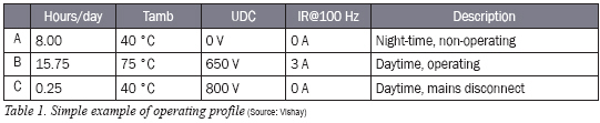
Film and aluminum capacitors have limitations that impact service life and reliability of the solar inverter. Therefore, you need to do a careful job of specifying variations in operating conditions over time. Important parameters are component ambient temperature, operating voltage, ripple current and duration. Table 1 provides an example of a very simple operating profile.
.jpg)
Capacitor Basics
Film and aluminum capacitors are two variations on the parallel plate capacitor. Figure 2 shows their basic construction, highlighting the main differences.
Film capacitors for use as the energy buffer in solar inverters consist of a winding of two layers of metalized polypropylene. The thickness of the polypropylene determines the voltage rating, which can go up to several kV. The metallization on the propylene is contacted by spraying metal droplets on the side of the winding. The terminal leads are welded on this metallization.
Aluminum capacitors consist of two layers of aluminum foil, separated by one or two layers of paper and impregnated by a conductive fluid, the electrolyte. The terminals are welded on each layers of aluminum. The first layer of aluminum is porous, to increase its surface area, and is covered with a thick oxide layer. The second layer of aluminum is only used to contact the electrolyte. The voltage rating is limited by the thickness of the oxide layer and the properties of the electrolyte, in practice to about 600 V.
Film vs. Aluminum Performance Characteristics
A film capacitor is almost an ideal capacitor. Its capacitance doesn’t change significantly with temperature and it hardly heats up when it is charged/discharged (ripple current). Due to its construction, the current paths are short, resulting in low inductance and allowing its use over a wide frequency range, usually up to several MHz.
Aluminum capacitors are more complex. The combination of thin pores and a not-so-conductive electrolyte result in a capacitance value that varies with temperature and frequency. Ohmic losses in the aluminum and paper/electrolyte combination and frequency-dependent losses in the imperfect oxide layer cause it to heat up when it is charged/discharged, resulting in a limited ripple current handling capability. And last but not least, as the electrolyte interacts with the other materials in the aluminum capacitor, the electrical characteristics change over time, leading to an increased failure rate after its end of life. As this rate of interaction goes down with the temperature of the capacitor, a lifetime calculation is needed based on the operating profile of the solar inverter.
If something goes wrong in a film capacitor, like a dielectric breakdown or a too high current pulse (high dU/dt), either the metallization or the contact to the metallization is damaged. In the end, the film capacitor becomes an open circuit.
If something goes wrong in an aluminum capacitor, the result is less predictable. The internal damage caused by a dielectric breakdown can end up as a short circuit, an open circuit, or something in between, such as an elevated level of leakage current. If the aluminum capacitor overheats and remains connected to the power, its temperature will rise above the boiling point of the electrolyte, about 200°C. The resulting internal pressure can cause the pressure relief to open, the electrolyte to escape and the winding to dry out.
.jpg)
Film vs. Aluminum Design Considerations
Performance isn’t everything when it comes to choosing between two technologies. The size of the component is also important. Price is also a factor. With this in mind, how do film and aluminum capacitors stack up?
Aluminum capacitors are definitely more space efficient than film capacitors. A 470 μF/450 V aluminum capacitor requires about 15% of the volume of a 470 μF/450 V film capacitor.
On the other hand, an aluminum capacitor has a limited lifetime and higher losses. For a solar converter that needs to work for 20 years or more with high ambient temperatures, or which has a high power rating, the lower losses and unlimited lifetime of a film capacitor make it a better choice
Based on component cost alone, an aluminum capacitor has a clear advantage, as the same 470 μF/450 V capacitor in film technology costs about five times more than its aluminum counterpart. However, aluminum capacitors typically require extra protection circuitry. Film capacitors, by contrast, require little in the way of external components to protect against failures. For solar inverters with high power ratings additional savings might be possible, for example by eliminating the water cooling for the energy buffer capacitors.
Selecting the technology for the energy buffer in a solar inverter is not a simple task. You need to consider a number of factors that may be related in subtle ways to component behavior. Therefore, it makes sense to choose a knowledgeable supplier and call on its design expertise early in the design process to ensure that the technology you choose will live up to all your requirements.
Theo van de Steeg is Manager Product Marketing of Vishay Aluminum Capacitors Division (www.vishay.com). He has been advising customers on the use of aluminum and other capacitor technologies since 1994. Before this, he worked several years as a design engineer for Tektronix after completing his electrical engineering study at the university of Eindhoven.
For more information, please send your e-mails to pved@infothe.com.
ⓒ2011 www.interpv.net All rights reserved. |


.jpg)