By Groupo clavijo
.jpg)
The PV sun trackers
First point to emphasize, saying each PV solar installation is unique. Therefore, before proceeding to choose any kind of PV sun tracker, we must analyze the working conditions under it’ll be operating: location of the site, topography, wind patterns, humidity... With these data, it would be possible to proceed, among other things, with the topographical layout showing the location of the PV sun trackers in the place of installation from shadow reports establishing the required distances between them to optimize the energy to produce.
PV Sun Tracker Design
Like any other high technology material, the solar tracker should be designed to comply with the requirements which will be required once it will be working: robustness and functionality. On the other hand, be sure to check the state of stress and strain against worst-stress situations.
A next-generation solar tracker should incorporate an independent program to monitor and manage any impacts through alarms (these can be managed directly in the solar tracker using a handheld console or integrated console through its internal monitoring or the Internet). Thus, the impact can be corrected quickly, reducing performance losses.
PV Sun Tracker Parts
At present, the dual-axis trackers (zenith and azimuth) are those that offer more performance, since they can always get the optimal orientation under which maximum efficiency is obtained. Structurally it has a pole, which also serves as a support element for mounting and fixing of electrical components, guard locked engines and hydraulic power, etc. In this way, it hides and keeps guard all the control elements increasing the security of the solar tracker and decreasing the chances of theft and damage by weather.
The joints have bronze bearings, oilers lubricated for proper operation and maintenance and integrated security systems, like hydraulic brake, limit switches for azimuthal rotation or physical stops on zenithal drive.
Other parts of the tracker are the orientation cogged reinforced crown for the azimuthal motion, independent trusses and rectangular profiles used for the bracing of the grill and fixing of solar panels. The design must take into account the ease of assembly of the panels as well as flexibility and tolerance to possible changes in them, something that is not unusual due to real life of the facility.
The Importance of Brake
A problem that may arise in the solar tracker during operation is the emergence of variable and alternating loads to which it is exposed, and can cause failure due to loss of capacity to generate mechanical force. In the medium-long term gaps that impede the ability of the solar tracker are produced. To avoid this, it is important that the solar tracker incorporates an automated hydraulic brake which eliminates the existing tolerances in the gear between the orientation cogged reinforced crown and the sprocket gear motor. In short, it extends the life of the solar tracker, getting more production.
Another important element of security in a solar tracker, and complementary to the first, is the electric brake. In the case of strong winds, it plays the roll of supporting the hydraulic brake and cushions the effect of wind on the tracker to avoid breakage. If you put both on opposite sides of the the orientation cogged reinforced crown then they share received efforts, ensuring that the movement as a ‘sailing ship’ is muffled and controlled.
Calculation of Forces in a Solar Tracker
The most sensitive parts to wear and breakage in a solar tracker are the azimuthal drive cinematic elements, i.e., the crown and gear. The function of these parts is to manage the correct position of the solar tracker grill in an azimuth angle coincides with the position of the sun, these two mechanisms do not have to endure the stresses transmitted by air pressure on the grill.
The structural rection of trackers has been studied, analyzed and validated by means of a numerical simulation with finite element. The load that is subjected solar tracker is defined by the force of the wind on the solar panels and the weight of the structure and photovoltaic modules.
The force exerted by the wind reaches its maximum when the solar panels at an angle of 45 degrees to the ground. The value of this force is defined by the following expression:
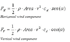
Where ‘p‘ is the air density, with an average value of 1.225E-12 T/mm3, ‘Area’ is the summation of the surface of 1,258 m2 panels (for a case of 176 panels); ‘v’ is wind speed, 33.3 m / s (120 km / h), ‘cd’ is the drag coefficient for a flat plate has a value of 1.1 and is the angle between the solar panels to the floor.
The images show the applied loads on the model.
In this section, the vibration frequencies characteristic of the structure were calculated (also using numerical simulation, finite elements) to verify that these modes themselves were far from being achieved in different working situations.
Once the wind stress on the grid was obtained and the voltage situation of the same was validated, the following elements to be analyzed and validated were the crown and gear.
The cogged crown must withstand axial loads included in the amount of vertical wind force and weight of the structure. The values stated above, the vertical wind force is 133.5 kN, and the weight of the own structure with PV Panels is 111.5 KN. As the axial load to be borne by the Crown is 245 KN.
The crown is also affected by the wind in the horizontal direction which will cause an overturning moment. The overturning moment at the crown is of 341 KN * m.
The rotation drive comprises a planetary gear motor with a M8 pinion of 14 teeth meshing to the cogged crown inside. The gear motor is formed by a motor of 0.33 kW with brake x.
When efforts to which it was submitted the crown and the gear were checked, a braking system which were not the one the gear itself already incorporates was devised after several months of design and testing prototypes, a system that was tested in wind turbines was finally chosen, this system is a hydraulic clamp called ‘hydraulic brake’, whose primary role is to support all efforts which the gear box and the crown were supposed to support.
Its operation is very simple: the controller sends a signal to an electrical relay and it sends the signal to a solenoid that opens one way to release the brake oil pressure. This is when the solar tracker can begin to rotate through the ramp up to provide the drive. When the solar tracker has finished making the motion, the brake is again activated, its inner chamber is filled with oil, reaching a high enough pressure for the solar tracker to maintain braking burst of air and if they were excessive, let slip the brake linings on the brake disc.
All these precise design of each of the many elements that make up the solar tracker, as well as the integration of these elements in the final set, finally achieve robustness, functionality and durability of them. In short, higher performance for solar photovoltaic installation.
Finally, and in order to further optimize the solar tracker, the following improvements should be incorporated:
-Monitored and customized remote control.
-Hydraulic protection system ensuring that, faced with power outages, the grill keeps in horizontal position reducing significantly the force of wind on the solar tracker when reducing the normal surface exposed.
-Use of anemometers with digital display, independent of solar trackers. In this way, you can set technical designs according to the needs of each client.
-Installation of data loggers to store wind records in three different sizes: internal memory, removable or remote connection via local or remote FTP.
-It is also advisable to carry out inspection and regular maintenance to ensure proper control and operation of solar trackers.
For more information, please send your e-mails to pved@infothe.com.
ⓒ2011 www.interpv.net All rights reserved. |


.jpg)