PV system designers have embraced distributed power electronics to reap additional kWh production, safety, and monitoring granularity. More than two million micro-inverters and DC-side optimizers have been projected to be installed in 20111). As with all other PV system components, market pressures demand constant improvements in cost, reliability and efficiency of today’s distributed power electronics solutions. If implemented correctly, the integration of these solutions directly onto the PV module is an ideal way to achieve such advances. This paper will discuss considerations for module OEMs and system designers who are contemplating the integration of smart electronics.
By Sam Arditi, Ron Hadar, Smriti Mishra
.jpg)
.jpg) Introduction to Smart Module Introduction to Smart Module
Rapid cost reductions and product innovation in Photovoltaic (PV) solar components have spurred continued market growth and are inching the Levelized Cost Of Energy (LCOE) of PV generated electricity towards that from conventional fossil fuel sources. One such key innovation that has been deployed widely is distributed power electronics within the Balance of System (BoS). The market requirement to eliminate production losses caused by string effects has led to increasing adoption of distributed technologies, such as DC optimizers or micro-inverters. When modules are connected in series, the string has a constant current and will be limited by the weakest module. Even ideally designed, un-shaded commercial systems have several sources of module mismatch, such as the variance in name-plate ratings, inconsistent module degradation, thermal mismatch, variable soiling, and cloud effects. Traditional solar installations incorporate central inverters with Maximum Power Point Tracking (MPPT) to set the single power-optimizing output level for the array. By contrast, Distributed Power Point Control at the module level enables optimal energy harvest from each module and can eliminate negative effects from weaker performing modules. This boost in energy production enhances revenues and greatly reduces the system’s LCOE.
Distributed power electronics can offer reliability, safety, and visibility benefits beyond increased energy harvest. Increased energy harvest ultimately improves reliability because modules function at peak power, reducing heat dissipation and strain on diodes. Safety benefits derive from module-level control that enables maintenance workers to cut off voltage at the module level eliminating high voltage on the home runs. System maintenance can be more targeted and much safer with this level of control. Operations and Maintenance (O&M) is also streamlined in systems with module-level visibility, as system owners can quickly pinpoint the specific module and problem that caused the energy loss. Issues may include broken panels, incorrect string wiring, arc faults, broken diodes, and incorrect grounding. Distributed electronics that monitor module-level data eliminate the need for expensive blanket maintenance and enable fewer and faster truck rolls.
There are three main approaches to distributing power electronics that reflect fundamentally different philosophies as to what is distributed. The first is a micro-inverter which moves the entire inverter to each module. This is the most hardware intensive approach as all inverter components are replicated for all modules. The module’s Direct Current (DC) output is converted to Alternating Current (AC) at each module and combines the output on a trunk cable to the AC grid connection. A second approach is to distribute only the inverter’s DC power stage (DC boosts and MPPT function) to the module. The DC/DC converter will achieve an optimized DC output from the module while keeping the AC conversion function at a central location. The approach greatly reduces the electronic complexity on each module but introduces an incremental power stage with a corresponding efficiency loss. A third approach for optimization advancement is impedance matching, where only simple sensing and output control is placed on the module. This is the lightest of all module-based electronic solutions as the maximum power point is calculated mathematically and the corresponding power is achieved by reflecting the correct ‘virtual’ impedance to each module. Each of these power optimization techniques result in different levels of efficiency, cost, and reliability that will affect the trend towards integrated products.
There are two options for integrating power electronics into a solar installation: modular or combined junction box. In the modular solution, the micro-inverter or DC optimizer is distinct from the junction box and is attached to each module’s frame or mounting structure. As an alternative solution, leading manufacturers of each distributed technology are either offering or developing an integrated ‘smart module’ solution, where the junction box is still attached to each module’s back sheet but it contains additional power optimization electronics (beyond the diodes). System benefits include optimizing energy production at the module-level, enhanced safety and module-level visibility. All smart modules offer net cost and reliability gains from reducing the total component count. They eliminate one enclosure, have fewer connection points, and ease installation since necessary power electronics will already be integrated with the module’s pre-existing junction box. The smart module can be sold by module manufacturers as a complete system solution.
The increased demand for an integrated solution often comes from PV owners and installers who have already experienced the benefits of incorporating power electronics and now seek to further reduce system and installation costs. Large developers have the greatest demand for integrated solutions over bolt-on modular solutions because their tight project margins imply high value in streamlininglabor and reducing installed hardwarecost. The market is quickly increasing in scale, evidenced by 2010 and 2011 results in the American market. The non-residential segment more than doubled in Q1 of 2011 over Q1 of 2010.2) Distributed commercial projects continue to be the largest segment in terms of solar market share. The trend towards growing industry scale favors increased adoption of an integrated solution for distributed technologies to optimize labor and installation cost reductions.
Technology Considerations
The central factors for evaluating any system technology are efficiency, cost, and reliability─all of which are interrelated. For example, a technology’s components affect both LCOE and reliability by adding to direct material cost and increasing potential points of failure with more electronic elements. Careful selection of the right integrated junction box requires assessing electronic components on each circuit board. Circuit boards provide important information about the quantity of components and quality of electrical design. There are several specific features to check for in addition to total component count: chip design, board layout, and component selection. Efficient solutions often incorporate chips with an Application-Specific Integrated Circuit (ASIC) that is designed to reduce component count. These chips can be more reliable and cost effective because they reduce the total component count and integrate electronic functions. For board layout, verify that sensitive components are not near the edges of the board to avoid potential damage. When evaluating component selection, note that a reliable solution should not include components where reliability is significantly degraded by thermal extremes (electrolytic capacitors are one such example).
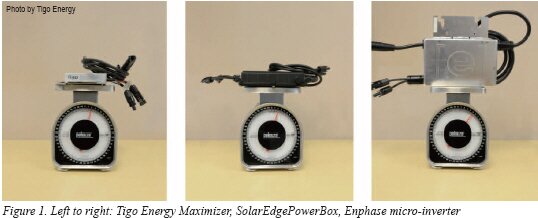
In addition to internal components, enclosure material also affects cost and reliability. Enclosure materials are either metal or plastic, where metal is notably heavier. The junction box is attached to each module’s back sheet and its weight is a source of physical strain. Compare relative sizes of each junction box as an initial evaluation of product weight. Weight is determined by component materials and volume of electronics. A standard junction box weighs approximately 1.4 lbs, or .64 kg, and uses plastic housing. Figure 1 shows modular distributed electronics solutions offered by Tigo Energy, SolarEdge and Enphase. The DC optimizers from Tigo Energy and SolarEdge each weigh approximately two pounds, with cables of the same length. The polycarbonate box from Tigo Energy includes weight from potting (encapsulation around electronic components), whereas the box from SolarEdge is not potted but includes weight from the metal enclosure. The Enphase micro-inverter weighs over five pounds, due to additional electronics for the AC conversion, potting and a metal enclosure.
Metal enclosures are not only heavier, but they are also more expensive, require additional wires for grounding, and reflect lower product efficiency. Products include metal walls on the enclosure when they require a heat sink to conduct thermal energy away from electronic components. In this way, the presence of metal can be proxy for assessing a product’s thermal generation and thereby efficiency. Hence, components can reflect information about all three critical factors: Reliability, cost, and efficiency.
Efficiency is obviously important for any system’s energy production and reliability of components, in part because a product with higher conversion efficiency will naturally result in a faster payback period. It is even more critical behind a module as efficiency losses directly convert into heat. Excessive heat has two effects, including a detrimental effect on module performance. Thermal generation is critical for an integrated junction box because the air gap between the electronics and the module is reduced or eliminated. A product’s thermal generation could increase temperature by approximately two degrees on the contacted surfaces for every percentage point drop in efficiency. Ultimately, increased heat dissipation of less efficient architectures effects long-term reliability and raises the LCOE.
When power electronics produce heat, they create hot spots on the solar module. Hot spots exacerbate module mismatch and escalate solar cell degradation. According to a recent NREL study3), a possible cause for cell degradation is current accumulating at the edges of hot spots. Standard junction boxes have nearly 100% efficiency, so they have almost no heat dissipation in normal operation (when the diodes are not active). Recent testing showed at STC (77˚F) that a micro-inverterexternal surface can heat up to 91.4˚F and remain at a higher temperature than the solar panel overnight. A smart module’s integrated junction box would keep all thermal generation close to the silicon. Constant exposure to heat will degrade a module more rapidly than the anticipated 25 year life. Hence, without addressing these thermal considerations, the system performance will suffer in both the short and long term: energy losses through low efficiencies, higher maintenance costs, and more module replacements due to accelerated degradation.
System -Level Considerations
As installers move towards project scale, they will realize gains from incorporating products with maximum design flexibility. A distributed technology that is compatible with all modules and all inverters will enable the greatest flexibility in commercial design. The smart module should operate equally effectively in all geographies and with all module sizes. Solar energy is a rapidly changing industry that can gain significantly from flexible designs that ease system upgrades at any part of the value chain.
When designing an installation, engineers evaluate necessary string length and module orientation with the ultimate goal of optimizing use of available space. System owners can take advantage of cost savings from having less wiring when they connect modules in longer strings. The distributed technology should also support strings with modules in different orientations. This ability allows system engineers to optimize use of available space to increase production and minimize cost.
To ensure long-term reliability, highly accurate, real-time data should be collected every couple seconds to add a layer of safety and operational efficiency. Real-time monitoring empowers system owners with alerts and detailed information about failures as soon as they arise. Combined with module-level data, system owners can pinpoint and repair failures quickly. This enables system owners to more closely enforce warranties and component manufacturers to incorporate a wealth of accurate data into their development cycle. Manufacturers of modules, micro-inverters, and DC optimizers should drive continuous improvement in the industry. New technologies and designs may be necessary at all parts of the value chain so collaboration will key. Product development cycles will hinge on the ease of compliance testing where a smoother process will shorten the time to market for final products.
Commercial Considerations
Once a decision has been made to develop a smart module product, it should be natural to look for the highest return on the R&D expense while addressing the broadest market. The first component of the equation is to minimize the risk and cost of development through the technology selection process. The ideal smart module will have minimal changes to current module architecture and would incorporate proven solutions. The path of least resistance for any module manufacturer’s research and development team will be electronics that are already compatible with the module’s power and voltage ratings, have a wide binning tolerance, and do not require additional grounding. The electronics should be manufactured quickly enough to keep pace with a rapid product development cycle so that a module manufacturer’s research team is not constrained by their electronics partner.
Commercialized products also improve system reliability by limiting risk. Distributed technologies with over 15 MW shipped each month have already been accepted by the market and should have proven themselves in a range of environmental applications. A commercialized solution in a light enclosure with minimum heat dissipation would be easiest to embed in a junction box and attach to a module back sheet, without significantly changing the proven technology.
The second key component to maximizing ROI is ensuring that the smart module product has the flexibility to address all system topologies and market geographies. The PV module today is a flexible horizontal building block that can be combined with many different BoS solutions to meet the needs of any system designer. The Smart Module should retain this flexibility rather than becoming a narrow component to a specific vertical BoS solution?limited in application, BoS vendor selection, or geographic acceptance. To avoid this, the distributed technology should be compatible with all modules, all inverters, and operate effectively in all geographies. Modules may not be compatible if the distributed electronics cannot support its power rating. As module manufacturers increasingly develop modules with a name-plate rating of 300 W and above, integrated products should incorporate power electronics that support this type of scale. Similarly, consider whether a new smart module only operates with a specific inverter manufacturer or requires unique wiring. Universal compatibility enables the widest proliferation of the solar energy sector.
The solar industry around the world is moving towards reduced costs and increased operational efficiency. Installations of all sizes attain the value of distributed electronics and benefit from cost advantages of the smart module integration. Solar installations must carefully balance cost reductions with potential risks to reliability and module degradation from using new integrated junction boxes. A careful evaluation of weight, heat dissipation, and reliability at the module-level will be a critical step in designing an optimized solar solution.
Sam Arditi is CEO and Co-Founder of Tigo Energy (www.tigoenergy.com). Ron Hadar is COO, Company President and Co-Founder of Tigo Energy. Smriti Mishra is Lead Technical Marketing Associate of Tigo Energy.
REFERENCES
1) M.J. Shiao. GTM Research
2) SEIA/GTM Research US Solar Market Insight: 1st Quarter 2011 Executive Summary
3) E. Molenbroek, D.W. Waddington , and K.A. Emery. Hot Spot Susceptibility and Testing of PV Modules. National Renewable Energy Laboratory
For more information, please send your e-mails to pved@infothe.com.
ⓒ2011 www.interpv.net All rights reserved. |